pat_uv = azel2uvpat( pat_azel , az , el ) expresses the antenna radiation pattern pat_azel in u/v space coordinates instead of azimuth/elevation angle coordinates. pat_azel samples the pattern at azimuth angles in az and elevation angles in el . The pat_uv matrix uses a default grid that covers u values from –1 to 1 and v values from –1 to 1. In this grid, pat_uv is uniformly sampled with a step size of 0.01 for u and v. The function interpolates to estimate the response of the antenna at a given direction. Values in pat_uv are NaN for u and v values outside the unit circle because u and v are undefined outside the unit circle.
pat_uv = azel2uvpat( pat_azel , az , el , u , v ) uses vectors u and v to specify the grid at which to sample pat_uv . To avoid interpolation errors, u should cover the range [–1, 1] and v should cover the range [–1, 1].
[ pat_uv , u_pat , v_pat ] = azel2uvpat( ___ ) returns vectors containing the u and v coordinates at which pat_uv samples the pattern, using any of the input arguments in the previous syntaxes.
Convert a radiation pattern to u-v space, with the u and v coordinates spaced by 0.01.
Define the pattern in terms of azimuth and elevation.
az = -90:90; el = -90:90; pat_azel = mag2db(repmat(cosd(el)',1,numel(az)));
Convert the pattern to u-v space.
pat_uv = azel2uvpat(pat_azel,az,el);
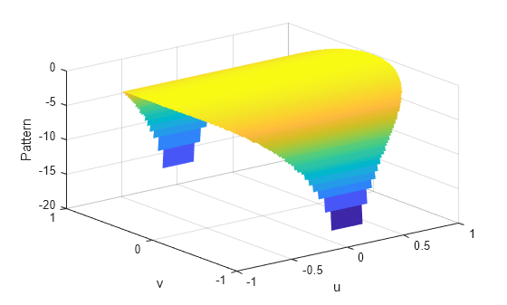
Plot the result of converting a radiation pattern to u / v space with the u and v coordinates spaced by 0.01.
The radiation pattern is the cosine of the elevation angle.
az = -90:90; el = -90:90; pat_azel = repmat(cosd(el)',1,numel(az));
Convert the pattern to u / v space. Use the u and v coordinates for plotting.
[pat_uv,u,v] = azel2uvpat(pat_azel,az,el);
Plot the result.
H = surf(u,v,mag2db(pat_uv)); H.LineStyle = 'none'; xlabel('u'); ylabel('v'); zlabel('Pattern');
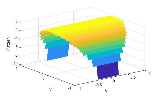
Convert a radiation pattern to u / v form, with the u and v coordinates spaced by 0.05.
The radiation pattern is cosine of the elevation angle.
az = -90:90; el = -90:90; pat_azel = repmat(cosd(el)',1,numel(az));
Define the set of u and v coordinates at which to sample the pattern. Then, convert the pattern.
u = -1:0.05:1; v = -1:0.05:1; pat_uv = azel2uvpat(pat_azel,az,el,u,v);
Plot the result.
H = surf(u,v,mag2db(pat_uv)); H.LineStyle = 'none'; xlabel('u'); ylabel('v'); zlabel('Pattern');
Antenna radiation pattern in azimuth/elevation form, specified as a Q-by-P matrix. pat_azel samples the 3-D magnitude pattern in decibels, in terms of azimuth and elevation angles. P is the length of the az vector, and Q is the length of the el vector.
Data Types: double
Azimuth angles at which pat_azel samples the pattern, specified as a vector of length P. Each azimuth angle is in degrees, between –90 and 90. Such azimuth angles are in the hemisphere for which u and v are defined.
Data Types: double
Elevation angles at which pat_azel samples the pattern, specified as a vector of length Q. Each elevation angle is in degrees, between –90 and 90.
Data Types: double
u coordinates at which pat_uv samples the pattern, specified as a vector of length L. Each u coordinate is between –1 and 1.
Data Types: double
v coordinates at which pat_uv samples the pattern, specified as a vector of length M. Each v coordinate is between –1 and 1.
Data Types: double
Antenna radiation pattern in u/v form, returned as an M-by-L matrix. pat_uv samples the 3-D magnitude pattern in decibels, in terms of u and v coordinates. L is the length of the u vector, and M is the length of the v vector. Values in pat_uv are NaN for u and v values outside the unit circle because u and v are undefined outside the unit circle.
u coordinates at which pat_uv samples the pattern, returned as a vector of length L.
v coordinates at which pat_uv samples the pattern, returned as a vector of length M.
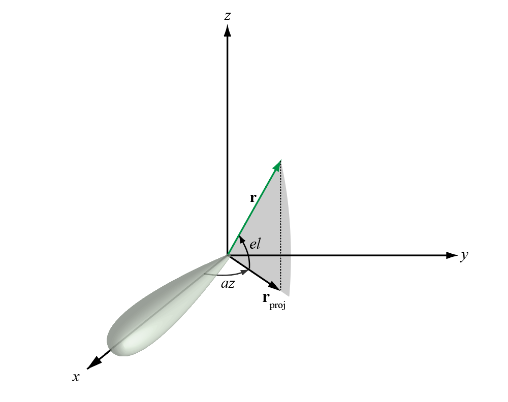
The azimuth angle of a vector is the angle between the x-axis and the orthogonal projection of the vector onto the xy plane. The angle is positive in going from the x axis toward the y axis. Azimuth angles lie between –180 and 180 degrees. The elevation angle is the angle between the vector and its orthogonal projection onto the xy-plane. The angle is positive when going toward the positive z-axis from the xy plane. By default, the boresight direction of an element or array is aligned with the positive x-axis. The boresight direction is the direction of the main lobe of an element or array.
Note
The elevation angle is sometimes defined in the literature as the angle a vector makes with the positive z-axis. The MATLAB ® and Phased Array System Toolbox™ products do not use this definition.
This figure illustrates the azimuth angle and elevation angle for a vector shown as a green solid line.
The u and v coordinates are the direction cosines of a vector with respect to the y-axis and z-axis, respectively.
The u/v coordinates for the hemisphere x ≥ 0 are derived from the phi and theta angles by:
u = sin θ cos ϕ v = sin θ sin ϕ
In these expressions, φ and θ are the phi and theta angles, respectively.
To convert azimuth and elevation to u and v use the transformation
u = cos e l sin a z v = sin e l
which is valid only in the range abs(az)≤=90.
The values of u and v satisfy the inequalities
− 1 ≤ u ≤ 1 − 1 ≤ v ≤ 1 u 2 + v 2 ≤ 1
Conversely, the phi and theta angles can be written in terms of u and v using
tan ϕ = v / u sin θ = u 2 + v 2
The azimuth and elevation angles can also be written in terms of u and v:
sin e l = v tan a z = u 1 − u 2 − v 2
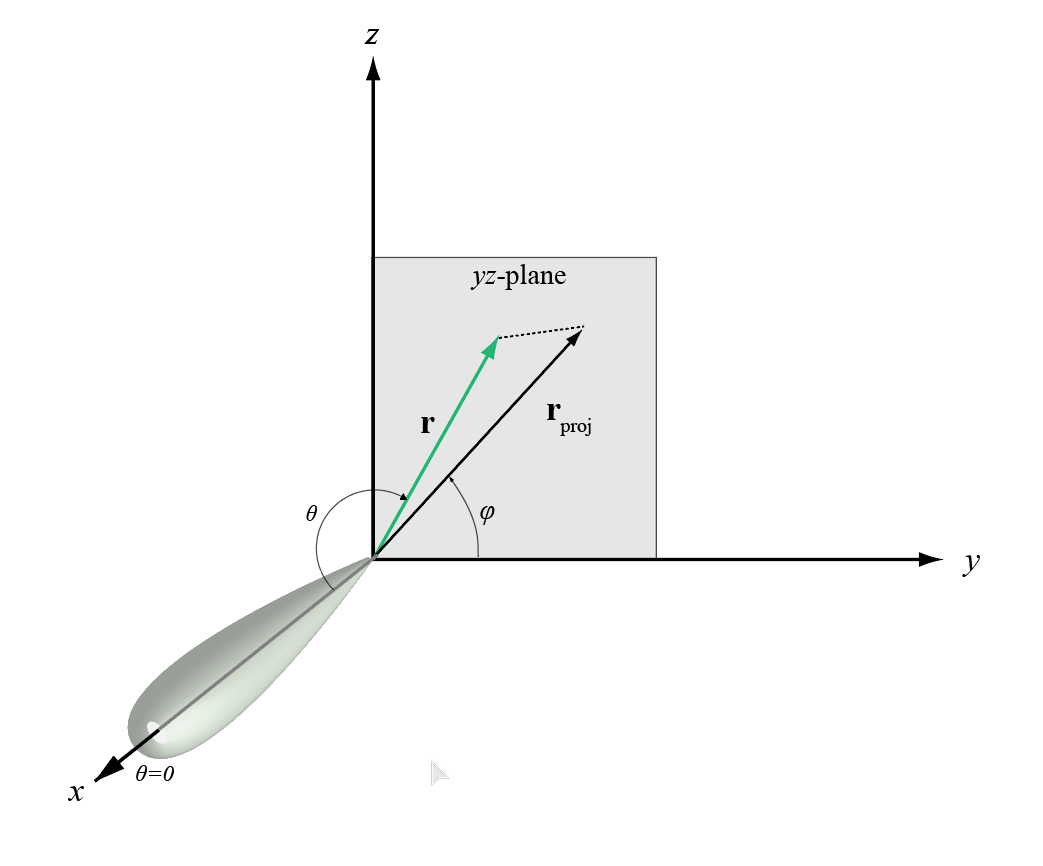
The phi angle (φ) is the angle from the positive y-axis to the vector’s orthogonal projection onto the yz plane. The angle is positive toward the positive z-axis. The phi angle is between 0 and 360 degrees. The theta angle (θ) is the angle from the x-axis to the vector itself. The angle is positive toward the yz plane. The theta angle is between 0 and 180 degrees.
The figure illustrates phi and theta for a vector that appears as a green solid line.
The coordinate transformations between φ/θ and az/el are described by the following equations
sin e l = sin ϕ sin θ tan a z = cos ϕ tan θ cos θ = cos e l cos a z tan ϕ = tan e l / sin a z
Usage notes and limitations:
Does not support variable-size inputs.
Introduced in R2012a